MIL-STD-1553B Avionic Data Bus
Introduction:
Originally an avionics data bus for use by the United States military, MIL-STD-1553 was first adopted in 1973 by the US Air Force and first used on the F-16 fighter jets. Subsequent revisions later (the latest at time of writing being revision C in 2018), and the data bus has been adopted in civil aerospace application, and in spacecraft, including on the James Webb space telescope and International Space Station.
It is now maintained by both the U.S. Department of Defence and the Society of Automotive Engineers. Outside of the US, and adopted by NATO, MIL-STD-1553 has been re-packaged with tweaks as STANAG 3838 and by the UK MoD as Def-Stan 00-18 part 2 where it has been used together with STANAG 3910 on the Eurofighter Typhoon.
Topology:
A MIL-STD-1553 network begins with a Bus Controller (BC) connected to wire pair of 70 Ω to 85 Ω impedance at 1 MHz. A shielded twisted pair, twinaxial, coaxial, and triaxial cable can all be used. The Bus Controller initiates all communications, sending commands at predetermined intervals.

Fig. 1 - MIL-STD-1553 Bus Topology Part 1
To the bus cable up to 31 compatible devices can be attached via coupling ‘stubs’, and isolation transformers either external or built into the device. The first of the devices we will connect are Remote Terminals (RT). Each Remote Terminal is assigned a unique 5 bit address, ranging from 0 to 30. Address 31 (binary 11111) is reserved for a special purpose, a broadcast mode which we shall come to later. The Remote Terminal receives and decodes the commands from the Bus Controller, and responds accordingly.

Fig. 2 - MIL-STD-1553 Bus Topology Part 2
A Remote Terminal might be either an interface between the MIL-STD-1553 and a subsystem, or built into the subsystem itself, for example an Air Data Inertial Reference Unit (ADIRU), a switch on the landing gear or lighting. It may also be a device bridging two MIL-STD-1553 buses.
Some installation will also include a Bus Monitor (BM) to passively record the traffic for later analysis. It may record all or a filtered subset of the bus messages including errors.

Fig. 3 - MIL-STD-1553 Bus Topology Part 3
The resilience of the bus is enhanced by the addition of a second wire pair to which the Bus Controller and Remote Terminals are be coupled. A fallback or backup Bus Controller can also be installed. N.B. Only one bus controller and one bus wire pair can be active at any one time.

Fig. 4 - MIL-STD-1553 Bus Topology Part 4
The bus cables must be terminated with a resistance equal to the cable’s nominal impedance, typically 78Ω, this helps to prevent disruption and intermittent communication failures.
Bit Representation and Bus Protocol:
Messages on a MIL-STD-1553 bus comprise of one or more 16 bit words. Words come in three types; Command, Data, and Status. Each bit is represented by a 1 µs Manchester Coded bi-phase pulse which conveys both data and clock. To aid synchronisation, each word is preceded by a 3 µs sync pulse and followed by an odd parity bit. Thus a word could be seen as 20 bits long. A longer 4 µs gap is introduced between messages with the expectation that all devices will broadcast a reply to a command within 4 to 12 µs. If after 14 µs a device has not responded, it is judged not to have received the command.
Manchester Code:
Also known as phase encoding (PE), Manchester Code merges data and clock pulse in an XOR gate, producing bits that either rise from low-to-high, or fall from high-to-low, midway through their duration.
There are two conventions as to how these rises and falls should be interpreted.
MIL-STD-1553 follows the original convention, published by G. E. Thomas in 1949. Here a 0 is represented with a low-to-high transition, whilst a 1 is represented by a high-to-low transition.
| Manchester Code XOR Gate | ||
| Data | Clock | Output |
| 0 | 0 | 0 |
| 1 | 1 | |
| 1 | 0 | 1 |
| 1 | 0 | |
Thus an example of Manchester encoded data for MIL-STD-1553 might be represented thus.
| MIL-STD-1553 Bit Manchester Bit Encoding | |||||||||||||||||||||||||||||||||
| Clock |
|
||||||||||||||||||||||||||||||||
| NRZ Data |
|
||||||||||||||||||||||||||||||||
| MIL-STD-1553 Manchester |
|
||||||||||||||||||||||||||||||||
Now let us look at the three word formats (Command, Data, and Status) a little more closely.
The Command Word:
Each MIL-STD-1553 command word is a 16-bit value that contains four fields; Remote Terminal Address, Transmit / Receive, Subaddress / Mode, and Data Word Count / Mode Code. This 16-bit value is sandwiched between a 3-bit long sync pulse at the front and a single parity bit at the end.
The diagram below shows the first transmitted bit on the left, the last on the right.
| Command Word Format | |||||||||||||||||||
| Sync. | Remote Terminal Address | T/R | Subaddress / Mode | Data Word Count / Mode Code | Parity | ||||||||||||||
| 1 | 2 | 3 | 4 | 5 | 6 | 7 | 8 | 9 | 10 | 11 | 12 | 13 | 14 | 15 | 16 | 17 | 18 | 19 | 20 |
We can rotate this table through 90° and expand it to include a full description.
| Command Word Format, Expanded | ||||||||||||||
| Section | Bit Count | Description | ||||||||||||
| Sync | 1 | To aid synchronisation, each word is preceded by a 3 µs sync pulse. The sync pulse is positive for the first half and negative for the second half. The sync pulse is invalid as a Manchester Code. |
||||||||||||
| 2 | ||||||||||||||
| 3 | ||||||||||||||
| Source Remote Terminal Address |
4 | This is the 5 bit address of the Remote Terminal designated to action the command. All but binary address 11111 (decimal 31) identify a unique Remote Terminal. Instead decimal 31 addresses all devices on a “Broadcast Mode”, if supported by the bus hardware. |
||||||||||||
| 5 | ||||||||||||||
| 6 | ||||||||||||||
| 7 | ||||||||||||||
| 8 | ||||||||||||||
| Transmit / Receive |
9 |
|
||||||||||||
| Subaddress / Mode |
10 |
|
||||||||||||
| 11 | ||||||||||||||
| 12 | ||||||||||||||
| 13 | ||||||||||||||
| 14 | ||||||||||||||
| Data Word Count / Mode Code | 15 | The Subaddress / Mode value (above) determines how these 5 bits are to be read, this will be either: a) The number of data words to be transmitted or received, where binary 00001 through to 11111 are 1 to 31 decimal, and binary 00000 is actually 32. b) The Optional Mode Code, expanded below. |
||||||||||||
| 16 | ||||||||||||||
| 17 | ||||||||||||||
| 18 | ||||||||||||||
| 19 | ||||||||||||||
| Parity | 20 | Used for error detection, this bit is used to ensure that the total number of 1 bits in the previous 16 bits is an odd number. For example the command word 10100 1 00101 01010 has 7 1 bits. This is already an odd number, so the parity bit will be set to 0. |
||||||||||||
The Optional Mode Control Code:
When multiplexed bus related hardware is used, and to assist with information flow management, the Data Word Count value on the Command Word may contain a Mode Code instead. As was shown above, this is determined by using a value of 00000 or 11111 in the Subaddress / Mode section.
The use of an Mode Code also affects the interpretation of the transmit / receive bit as described below.
Mode Codes 00000 to 01111 reference modes that do not require the transfer of a data word. In these cases the T/R bit should be set to 1.
Mode Codes 10000 to 11111 reference modes that expect the transfer of a single 16 bit data word. In these cases the T/R bit indicates the direction of the transfer along the lines prescribed above.
Here’s a table of the Mode Codes and their functionality.
| MIL-STD-1553 Mode Control Code: | |||||
| T/R | Mode Control | Function | Description | Data Word |
Broadcast |
| 1 | 00000 | Dynamic Bus Control | Hands control of the bus to a RT. If the RT declines, the existing bus controller retains control. | No | No |
| 1 | 00001 | Sync. | Reset the internal timer of an RT, initiate a sequence, etc.. | No | Yes |
| 1 | 00010 | Transmit Status Word | Causes an RT to transmit the status word associated with the previous valid command so that the BC can confirm receipt. | No | No |
| 1 | 00011 | Initiate Self-Test | Causes an RT to begin a self-test and the transmit it’s status. | No | Yes |
| 1 | 00100 | TX Shutdown | Disables the TX associated with the current redundant / backup bus. | No | Yes |
| 1 | 00101 | Override TX | Enables the TX associated with a previously disabled redundant bus. | No | Yes |
| 1 | 00110 | Inhibit Terminal Flag Bit | Sets the T/F bit in the status word to logical zero unless otherwise commanded. | No | Yes |
| 1 | 00111 | Override Inhibit Terminal Flag Bit | Resets the Inhibit Terminal Flag bit. | No | Yes |
| 1 | 01000 | Reset Remote Terminal | Resets an RT to the default power up initialised state. | No | Yes |
| 1 | 01001 | Reserved | Not currently used. | No | TBD |
| 1 | ..... | Reserved | Not currently used. | No | TBD |
| 1 | 01111 | Reserved | Not currently used. | No | TBD |
| 1 | 10000 | Transmit Vector Word | Cause the RT to transmit a status word and a data word containing service request information. | Yes | No |
| 0 | 10001 | Sync. | The RT shall receive a Command Word followed by a Data Word containing sync. information for the RT. | Yes | Yes |
| 1 | 10010 | Transmit Last Command | Causes an RT to transmit its Status Word. | Yes | No |
| 1 | 10011 | Transmit Built-In-Test Word | Causes an RT to transmit its Status Word followed by a single Data Word containing the Built-In-Test (BIT) data. | Yes | No |
| 0 | 10100 | Selected TX Shutdown | Causes an RT to disable the TX associated with a specific redundant bus. | Yes | Yes |
| 0 | 10101 | Override Selected TX | Enables a TX previously disables by the Selected TX Shutdown command. | Yes | Yes |
| 0 or 1 | 10110 | Reserved | Not currently used. | Yes | TBD |
| 0 or 1 | ..... | Reserved | Not currently used. | Yes | TBD |
| 0 or 1 | 11111 | Reserved | Not currently used. | Yes | TBD |
where TX = Transmitter
The Data Word:
Each MIL-STD-1553 data word is a 16-bit value sandwiched between a 3-bit long sync pulse at the front and a single parity bit at the end. These contain the information being sent to or from a Bus Controller or Remote Terminal. A maximum of 32 Data Words may follow a Command Word.
The diagram below shows the first transmitted bit on the left, the last on the right.
| Data Word Format | |||||||||||||||||||
| Sync. | Data | Parity | |||||||||||||||||
| 1 | 2 | 3 | 4 | 5 | 6 | 7 | 8 | 9 | 10 | 11 | 12 | 13 | 14 | 15 | 16 | 17 | 18 | 19 | 20 |
The Status Word:
Each MIL-STD-1553 status word is a 16-bit value containing ten values / flags, sandwiched between a 3-bit long sync pulse at the front and a single parity bit at the end.
The diagram below shows the first transmitted bit on the left, the last on the right.
| Status Word Format | |||||||||||||||||||
| Sync. | Remote Terminal Address | ME | I | SR | Reserved | BC | B | SF | DBC | TF | Parity | ||||||||
| 1 | 2 | 3 | 4 | 5 | 6 | 7 | 8 | 9 | 10 | 11 | 12 | 13 | 14 | 15 | 16 | 17 | 18 | 19 | 20 |
We can rotate this table through 90° and expand it to include a full description.
| Status Word Format, Expanded | ||||||||||
| Section | Bit Count | Description | ||||||||
| Sync | 1 | To aid synchronisation, each word is preceded by a 3 µs sync pulse. The sync pulse is positive for the first half and negative for the second half. The sync pulse is invalid as a Manchester Code. |
||||||||
| 2 | ||||||||||
| 3 | ||||||||||
| Source Remote Terminal Address |
4 | This is the 5 bit address of the Remote Terminal transmitting the Status Word. All but binary address 11111 (decimal 31) identify a unique Remote Terminal. Decimal 31 addresses all devices on a “Broadcast Mode”, if supported by the bus hardware. |
||||||||
| 5 | ||||||||||
| 6 | ||||||||||
| 7 | ||||||||||
| 8 | ||||||||||
| Message Error | 9 |
|
||||||||
| Instrumentation | 10 | Used to aid the distinction between Command and Status Word. Usually set to logical zero. | ||||||||
| Service Request | 11 | Optional bit used to request the Bus Controller to carry out a predefined action. | ||||||||
| Reserved | 12 | |||||||||
| 13 | ||||||||||
| 14 | ||||||||||
| Broadcast Command | 15 |
|
||||||||
| Busy | 16 |
|
||||||||
| Subsystem Flag | 17 |
|
||||||||
| Dynamic Bus Control Acceptance | 18 |
|
||||||||
| Terminal Flag | 19 |
|
||||||||
| Parity | 20 | Used for error detection, this bit is used to ensure that the total number of 1 bits in the previous 16 bits is an odd number. For example the command word 10100 1 00101 01010 has 7 1 bits. This is already an odd number, so the parity bit will be set to 0. |
||||||||
Message Formats:
Ten types of message format are defined by MIL-STD-1553B.
The first six are information transfer formats and are shown below where ...
| # | Indicates an inter-message gap. |
| ** | Indicates the response time. |
| RX | Receive. |
| TX | Transmit. |
| Bus Controller to Remote Terminal Transfers | ||||||||||
| RX Command | Data Word | Data Word | ••••• | Data Word | ٭ ٭ | Status Word | # | Next Command | ||
| Remote Terminal to Bus Controller Transfers | ||||||||||
| TX Command | ٭ ٭ | Status Word | Data Word | Data Word | ••••• | Data Word | # | Next Command | ||
| Remote Terminal to Remote Terminal Transfers | ||||||||||
| RX Command | TX Command | ٭ ٭ | Status Word | Data Word | ••••• | Data Word | ٭ ٭ | Status Word | # | Next Command |
| Mode Command without Data Word | ||||||||||
| Mode Command | ٭ ٭ | Status Word | # | Next Command | ||||||
| Mode Command with Data Word (TX) | ||||||||||
| Mode Command | ٭ ٭ | Status Word | Data Word | # | Next Command | |||||
| Mode Command with Data Word (RX) | ||||||||||
| Mode Command | Data Word | ٭ ٭ | Status Word | # | Next Command | |||||
| Four message types are broadcast information formats. | ||||||||||
| Bus Controller to Remote Terminal Broadcast | ||||||||||
| RX Command | Data Word | Data Word | ٭ ٭ | Data Word | # | Next Command | ||||
| Remote Terminal to Remote Terminal Broadcast | ||||||||||
| RX Command | TX Command | ٭ ٭ | Status Word | Data Word | ••••• | Data Word | # | Next Command | ||
| Mode Command without Data Word | ||||||||||
| Mode Command | # | Next Command | ||||||||
| Mode Command with Data Word (RX) | ||||||||||
| Mode Command | Data Word | # | Next Command | |||||||
MIL-STD-1553B in Data Acquisition:
Heim / Safran Data Systems flight test recorders and data acquisition units can accept multiple MIL-STD-1553B data channels on separate physical inputs. Depending upon configuration and bit rate, they are able to record all the messages on the bus, or strip out only those messages defined as of interest
Input Modules for the MDR Data Recorder

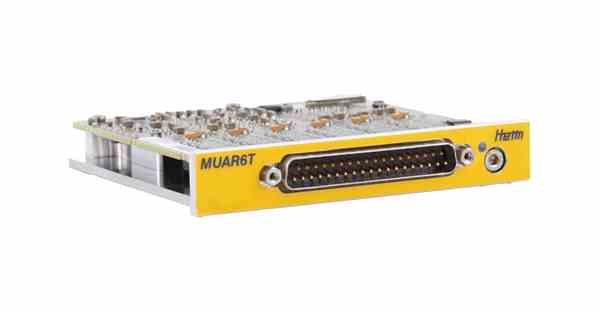
MUAR6T, MUAR6TA
The MUAR6T and MUAR6TA are 6 channel ASCB / MIL-STD-1553 input modules with transformer coupling.

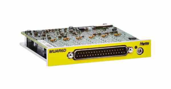
MUAR6D
The module accepts 6 independent, direct coupled, dual-redundant MIL-STD-1553B busses.

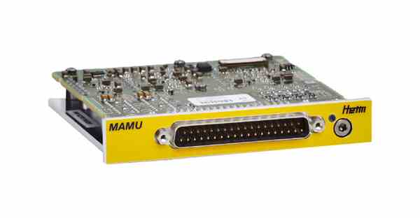
MAMU
The MAMU module supports 2 dual –redundant MIL-STD-1553B input channels, 2 PCM input channels and 8 ARINC 429 input channels.
Input Module for the XMA Data Acquisition Unit

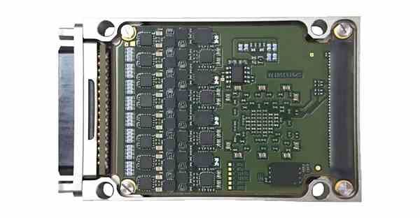
XMA MIL - 4 MIL-STD-1553 Channels
-
4 independent (or 2 redundant) MIL-STD-1553B bus monitoring with native 1553 electrical level or 2 independent (or 1 redundant) MIL-STD-1553B bus monitoring with RS422 electrical level.
-
Short (direct coupling) or long (transformer coupling) stub.
-
Parsing on all 1553 message types.
-
Message time stamping on parity bit of the first word of the message (with 1μs resolution).
-
Lightning protection (DO-160G)
Disclaimer: The information in this guide is designed to help you understand our products. It is correct to the best of our knowledge and at the time of writing. However Photo-Sonics International Limited does not accept any liability for its use. Instead the latest documentation from the relevant authority should be consulted.